

GUIDE TO THE WATERMILL
Stanway Mill is located in Church Stanway on the Stanway Estate, beneath the 600-foot-high Cotswold escarpment.
The Lidcombe springs, which issue from the junction between the impervious Upper Lias Clay and the overlying porous Inferior Oolite limestone, form the Papermill Stream, which in 1291 was recorded as powering four mills in the parish belonging to the Abbott of Tewkesbury.
The stream, which used to flow along the valley floor, had by that date been diverted along the contour to the mill pond which acts as a reservoir for Stanway Mill.
Once the water has flowed through the mill it passes below the yard in front of the mill, and thence back into the (culverted) stream, which joins the River Isbourne at Wormington and eventually flows into the Avon at Evesham.
HOW IT WORKS
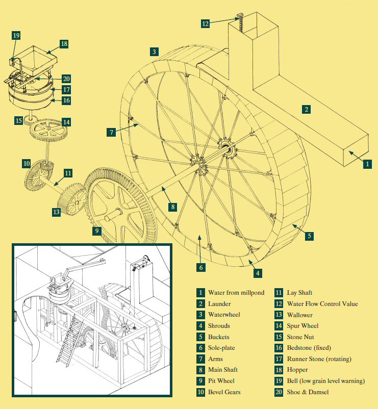
Water from the Papermill stream, which would normally rush down the stone-lined cascade south of the mill pond (1), is diverted into the mill pond when the sluice is lowered, and is held there by the retaining wall.
From the mill pond, water enters the mill through the launder (2) at the top floor level and, if the guillotine gate is open, flows onto the galvanised steel buckets at the top of the 24- foot diameter overshot cast iron waterwheel (3).
The rotating shaft (8) of the waterwheel drives the pit wheel (9).
The hardwood teeth of the pitwheel turn the iron teeth of the bevel gear (13), which in turn drives the horizontal lay shaft (11), the second bevel gear (10), the wallower, the spurwheel (14), the stone nut (15), and finally the runner stone (17). The purpose of this gearing is to increase the speed from the 6 rpm (revolutions per minute) of the waterwheel to the 80 rpm of the runner stone, which is optimum milling speed.
When sacks of corn are received at the mill, they are hoisted to the top or bin floor by the sack hoist. Gearing from the pitwheel drives a canvas belt on the top or bin floor. When the miller pulls a cord that runs up through the mill, he thereby tightens the belt against the chain drum of the sack hoist, causing the chain to haul the sack up to the top of the mill. Alternatively, nowadays, corn is delivered in bulk and literally blown through pipes to the storage bins on the top floor.
A chute from each bin leads to a hopper (18) above the millstone on the floor below (the stone floor). From there the corn is shaken into the “eye” or centre (20) of the upper or runner stone (17). The bottom or bedstone (16) stays still and the runner stone revolves. Both stones have a set of offset grooves or furrows cut into them. The corn is forced into the small space between the two stones where the action of the furrows crossing each other breaks the corn down to form flour.
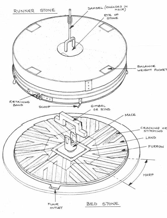
The miller, standing on the ground floor, can adjust the gap between the stones using a screw. If the flour feels too coarse, he screws down the runner stone so the stones grind more closely together. If the flour is too fine, he does the opposite. He can also regulate the amount of corn falling between the stones by turning a twist- peg one way or another. Attached to it is a cord connected to the “shoe” (20) delivering the corn to the stones. Raising and lowering the shoe controls the flow of the corn. Close by is the wheel controlling the amount of water flowing through the launder (12) and over the waterwheel and thus the speed of the wheel, so the miller has all the controls he needs in one place.
The flour is thrown outwards by centrifugal force to the outside of the stones and falls through a chute to the floor below (the ground floor) where it is either bagged as wholemeal flour or passes into a conveyor by which it is carried to the top of the mill to drop into a flour grader. Here, brushes rotating at about 350 rpm inside a cylinder lined with three different grades of metal gauze separate the flour into fine, middling or coarse grades. The bran falls out of the end of the cylinder. Chutes are positioned under the grader and carry the different grades of flour back to the ground floor where it is bagged for dispatch.
The flour is thrown outwards by centrifugal force to the outside of the stones and falls through a chute to the floor below (the ground floor) where it is either bagged as wholemeal flour or passes into a conveyor by which it is carried to the top of the mill to drop into a flour grader. Here, brushes rotating at about 350 rpm inside a cylinder lined with three different grades of metal gauze separate the flour into fine, middling or coarse grades. The bran falls out of the end of the cylinder. Chutes are positioned under the grader and carry the different grades of flour back to the ground floor where it is bagged for dispatch.